Individual Flow Complete

The digital design flow is complete. RJ has sent me the synthesis libraries that he had converted. I have tested them using Leonardo Spectrum for a simple counter. I then simulated the synthesised counter at behavioural level using ModelSim. After that I simulated it at transistor level using Eldo. Both work and produce similar results.

Note: VHDL vectors should be numbered in ascending order, i.e. 0 to 7 instead of 7 to 0. This is because EZWave doesn’t seem to allow me to reorder the individual bits of a bus. As a result the counter counts 0, 128, 64 …. instead of  0, 1, 2 ….

As for the analogue flow, I have managed to design, layout and simulate a simple custom NOR2 gate. So, that is working as well.

I should think that we should work out the details of the final design, so that I can start writing up the individual flows while I work out the integrated flow.

Analogue Flow

I’ve had some success with the analogue toolchain.

The previous problem with the ELDO simulation had been solved. The problem wasn’t with the model netlisting but the library inclusion. When the correct library is included, the custom models are found. I had assumed that the correct library would be included by default, which wasn’t the case. The library has to be explicitly selected using the built in design kit menu command. This allows the selection of various values: worst, typical, best. So, ELDO simulation at the transistor level works.

The next issue I faced was with SDL layout. The default transistors generated by Mentor will not pass LVS as they do not include substrate taps. Therefore, the generated devices need to be changed from “cgc” to “cgct” in order to include the taps. However, where “t” appears depends on the design. So, the students will need to experiment with the positioning of the substrate tap. Routing should be done manually using IRoute instead of auto-routing with ARoute. Otherwise, it may not meet DRC checks.

I have also successfully used Calibre to perform the LVS checks. I haven’t had time to do DRC/PEX but the AMS website does have instructions for them. Performing all the necessary modifications in order to meet DRC may be troublesome. I’ll need to keep track of all the different design rules. I’ve downloaded the document and I may print it out for reference.

Once all the issues have been resolved, I will try to do a mixed layout using ICStudio. The AMS website doesn’t have instructions for mixed designs. It does have instructions for standard cell layout. So, it might be necessary to do the analogue and digital layouts separately before integrating them only at the top-level of the chip.

Digital Flow

The digital tool flow should work without any problems.

snapshot30.jpg

I’d suggest using Emacs to write the VHDL code as it has a built-in language mode that is extremely helpful by ensuring that code is written in correct syntax. The built-in mode also checks the syntax using Modelsim. Modelsim will also simulate the digital code without any problems.

snapshot32.jpg

Leonardo can be run under WINE in full GUI mode without problems. It can synthesise the digital design using standard cells. RJ says that he will convert the libraries for us as soon as he can. So, we should be able to synthesis VHDL code to the AMS 0.35 standard cells. It is important to output the final synthesised netlist in Verilog. This will allow it to be imported into ICStudio for back-end work.

The synthesised netlist should simulate under Modelsim as well. I have already imported the AMS 0.35u VITAL, Vtables, Vcomponent VHDL libraries into Modelsim’s own internal library.

VLSI Toolchain Update

I’ve managed to get most of the Mentor toolchain working together. At present, I’m testing it with the following software versions:

  • ICFlow 2006.1 (this is the latest version of Mentor that supports the AMS 0.35u DK)
  • AdMS 2005.3 (this is listed as compatible with both ICFlow 2005.1 and 2006.1)
  • Calibre 2006.1 (this seems to work correctly so far)
  • LeonardoSpectrum 2005b
  • Modelsim 6.1b

I’ve stuck all the customisations in /usr/local/apps/mentor/AMS_Linux/cuedlib/. This includes: startup scripts that set all the necessary environment variables in /bin, compiled digital libraries for Modelsim simulation (C35_CORELIB) in /modelsim.

This is a potential process flow for the project. It would be possible to split the project by digital/analogue. DMH has suggested that it might be useful to get the students to build a transmission gate for the analogue side instead of just a random logic gate. He also suggested that a DVM might be a suitable project if we can get access to the AMS 0.35u analogue cells. According to the AMS website, they have opamps, dac, adc,comparators and much more. I’ve already mailed EUROPRACTICE to find out if we can get a copy of the analogue cells.

Assuming that we get the analogue cells, I would imagine that it’ll slot into the standard SDL flow. Then, we should be able to design a fairly complex analogue sub-system. Then, the digital sub-system will also need to be more complex. For the DVM, it should be more than just a simple counter.

Process Flow

AMS 0.35u HitKit 3.70 Update

Hierarchical Layout
ECB has successfully installed the latest HitKit and I have taken it for a test. It does not work with the latest Mentor ICFlow 2007. However, it is able to work with the slightly older 2006 version. It integrates nicely with ICStudio, allowing a more intuitive work flow than the older 3.51 HitKit. However, as the present installation of ICFlow 2006 doesn’t work with the installed simulator, I am unable to test out either device level (analogue) simulation, nor cell level (digital) simulation. I could also not test Calibre as the installed version is too new to work with the HitKit.

We’ve notified JPN that we’d like to install the supported versions of Mentor tools from EUROPRACTICE. The tools versions are slightly older than the ones we have installed. Hopefully, they’ll work nicely together.

While waiting for ECB to install the latest HitKit, I wrote a bunch of Verilog netlists for the standard devices as were part of the previous VLSI project, such as the counter, shift register and gates. A full parts list available in the standard cell library is available here:

http://asic.austriamicrosystems.com/databooks/index_c35.html

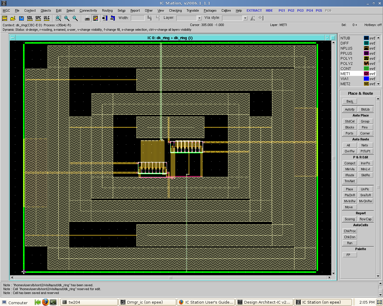
I then followed the instructions provided by AMS to bring a ring-oscillator design into final layout. The screenshot is of the tiny ring oscillator, surrounded by 2 output buffers, 1 input buffer, VCC, GND. It also has corner cells and filler cells. The instructions are given here:

http://asic.austriamicrosystems.com/hitkit/hk370/icstation/index.html

I was successful in:

  1. Importing a Verilog netlist into a schematic/symbol.
  2. Creating all the viewpoints (device, cell, apar) from the generated schematic.
  3. Using the generated schematics inside a top level wrapper with I/O pads.
  4. Doing a hierarchical layout of this design, with I/O pads, corner cells and filler cells from the HitKit.

I can assume that simulation should work, once the tools are installed properly. I have previously been able to simulate the design with the 2007 version of ICFlow. I will also assume that Calibre should work, as the instructions from AMS clearly state the necessary steps to perform verification.

Therefore, I can quite confidently say that we can build a design project out of this toolchain + design kit, once the other tools are correctly installed.

Tasks that need to be done:

  1. Choose a suitable design that can be built easily, using limited standard cell parts. Essentially, there are flipflops (D, T, JK), logic gates (XOR, XNOR, NOR, NAND, INV), adders (1-bit HALF, FULL), muxes, latches. The full parts list also provides speed, power and area estimates, which may be useful for deciding which parts to use.
  2. Adapt the instructions given by AMS into a manual. Although the steps are generally quite clear, the selections only make sense to someone who has done it before. Some information may need to be provided to help them understand how to do the top level integration of the design.

I would propose that the project be done in the following manner:

  • Week #1: Bring them through a quick design of a single ring oscillator, using standard cells, from HDL through to final layout. The idea is to familiarise themselves with the flow and toolchain. It took me about 2 hours to go through the motions. So, 8 hours should be sufficient for design import (they can look at the code/schematic), simulation (cell/device), layout.
  • Week #2: Get them to do their design in structural HDL, simulation and verification. All this can be accomplished from within ICStudio although other tools may be better. Emacs has a built in VHDL mode and a Verilog mode can be downloaded from the net.
  • Week #3: Design a custom NAND/NOR gate from transistor, simulation and verification. Integrate this gate into a new ring-oscillator.
  • Week #4: Bring their final design through to layout, LVS, DRC, XRC.
  • Week #4: (Optional) Verification of post layout design, using back annotation + possibly SDL.

New DK in the pipeline

I’ve just received an email from EUROPRACTICE today, with regards to our request for a newer DK. SM has told me that they will make the 3.70 version of AMS 0.35 available to us. However, they will require some license numbers from us. I have just checked the AMS 0.35 documentation and it is fully certified to work with Mentor 2005 tools. When we get the new DK, I will test them with the 2006 and 2007 toolchains to see if they work. Otherwise, we may need to get the 2005 version instead. The trouble with the 2005 and 2006 versions is that they don’t seem to work with Anacad2006.

DK Update

screenshot.png

I’ve done some more work on the 0.35u DK today. I can now do Auto Place & Route using standard cells. The I can auto layout a ring-oscillator design using standard cell NOR20 cells. I had previously succeeded laying out a custom NOR2 gate using the DK transistors. So, schematic to layout for both standard and custom cells work. However, I’ve yet to try laying out a ring-oscillator using purely custom cells and mixed custom/standard cells.

I am unable to do any LVS, DRC, PEX checks as Calibre doesn’t work with the current RULES file. SJM will need to install an older version of Calibre before I can test it out. I have also NOT yet been successful at simulating digital designs under MODELSIM.

NOTE: The correct SYMBOL and VIEWPOINT needs to be created from within DA-IC before we can do APR using IC.